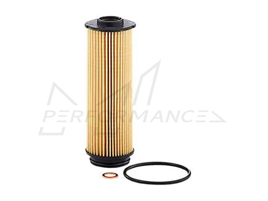
Filter Housing Assembly
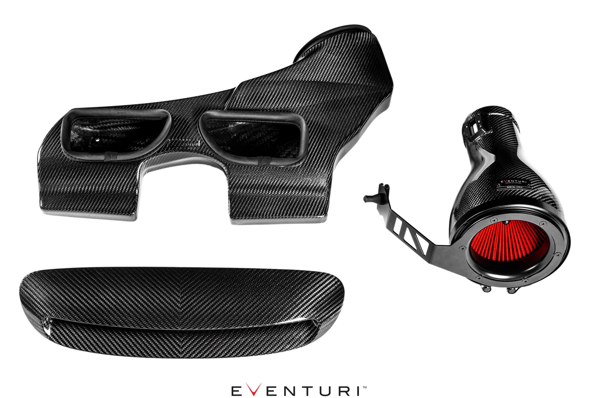
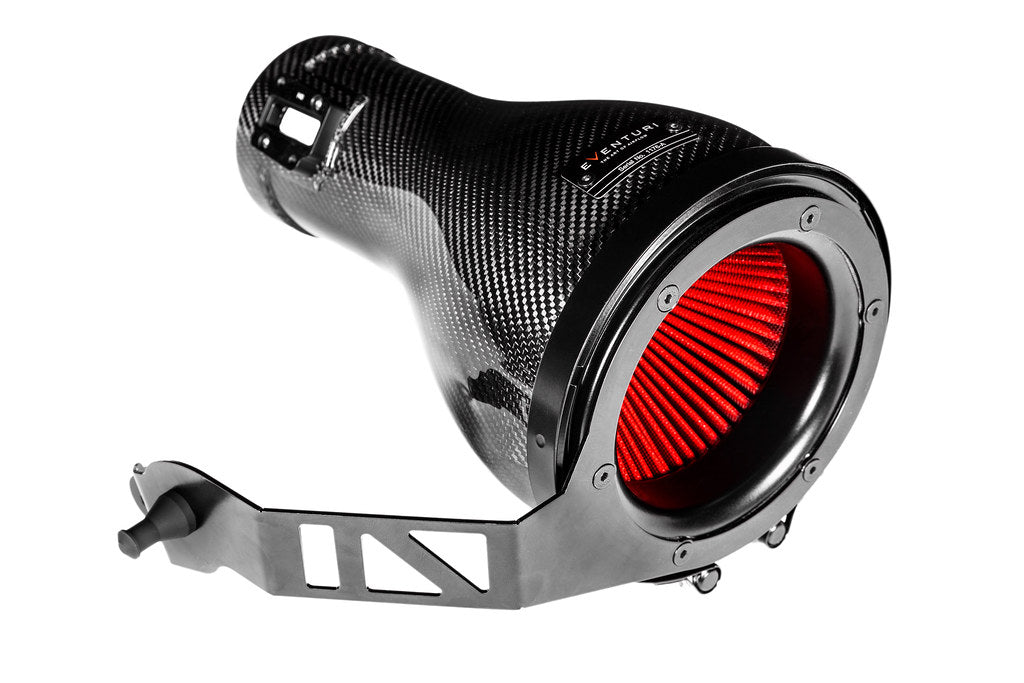
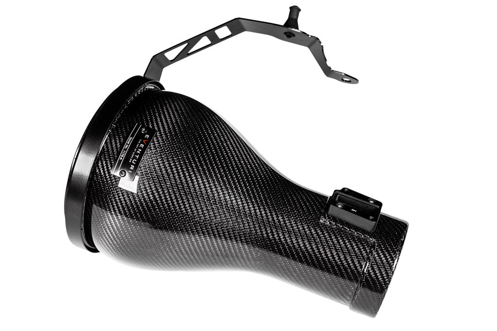
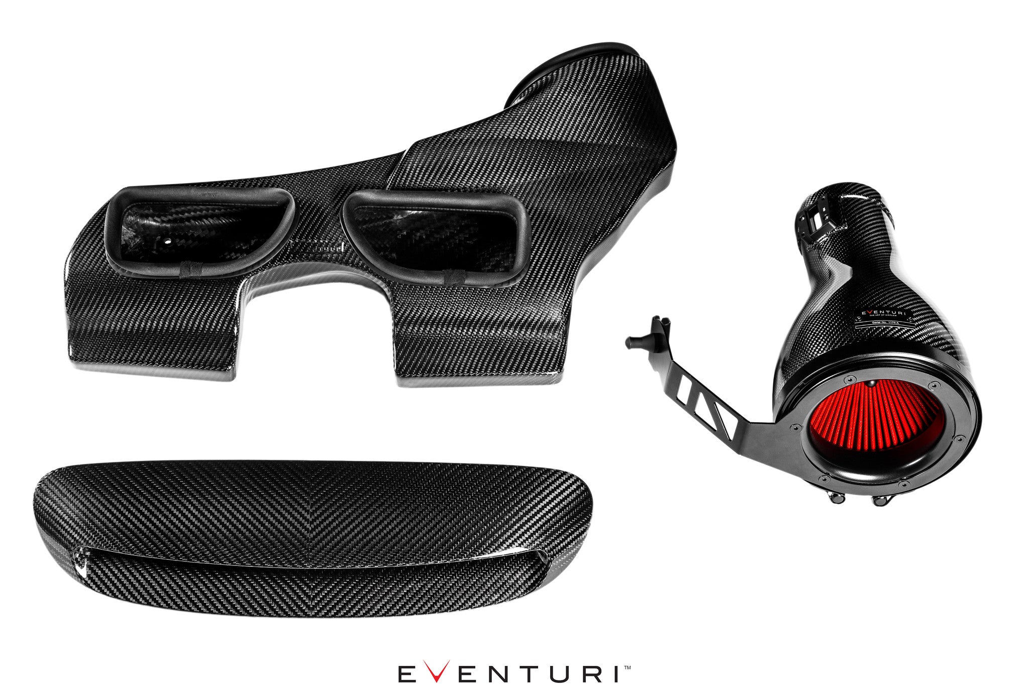
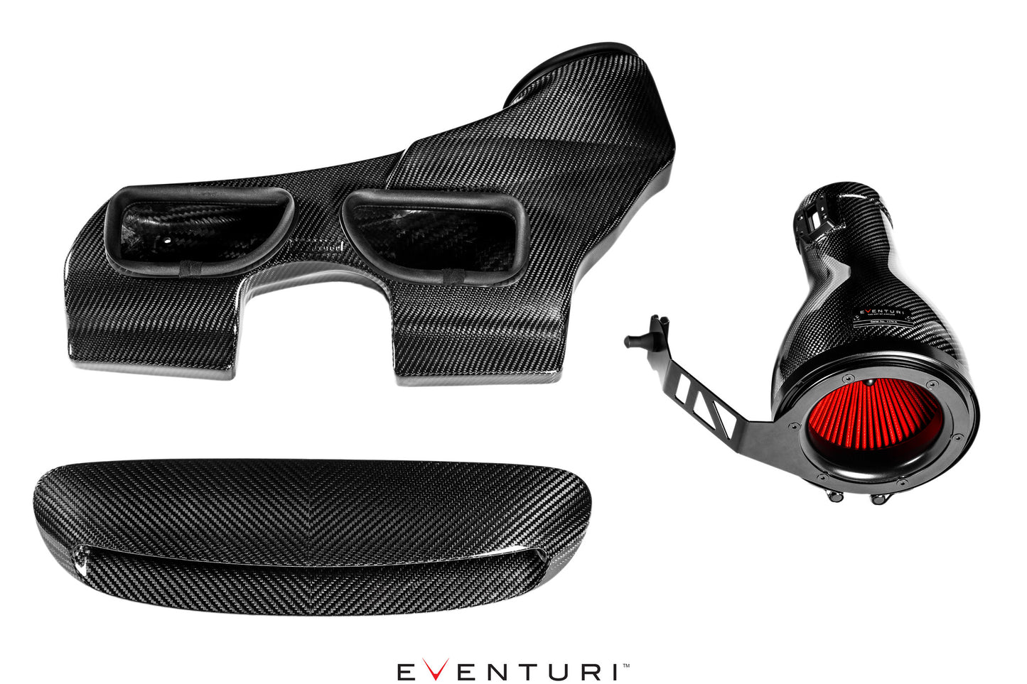
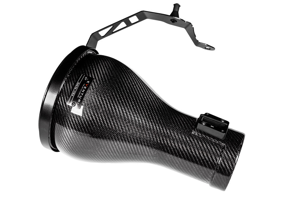
The filter housing comprises of our bespoke generation 2 filter, aluminium inlet cowl, stainless steel bracket and the integrated MAF section. The carbon pod shrouds the reverse mounted filter and smoothly shapes the airflow down to the MAF section which then connects to the stock inlet tube. This changes the flow path from the OEM airbox where airflow enters the front of the airbox, changes direction by 90 degrees to travel through the panel filter and then changes direction again by 90 degrees to move through the MAF section. Our system is a lot more direct with airflow entering the front of the filter housing and and moving into the MAF section without any abrupt direction changes. The result is a smoother path from the filter to the turbo inlet tube and therefore the turbo is able to function with less drag.

Patented Technology
Our patented filter housing has a smooth reduction in cross sectional area as it shrouds the filter and tapers down to the tubing. This geometry invokes the Venturi effect where the airflow accelerates whilst maintaining laminar conditions. It can be thought of as a large velocity stack - below is a diagram to show the comparison between our patented design and a regular intake system. Our bespoke filters aid the airflow moving through the housings and allow for an even velocity profile as the airflow exits the housings. Further details can be read in the Technology and Filters pages.

Carbon Intake Scoop
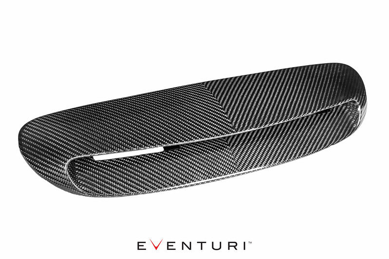
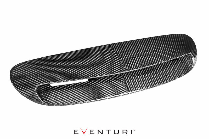
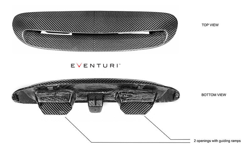
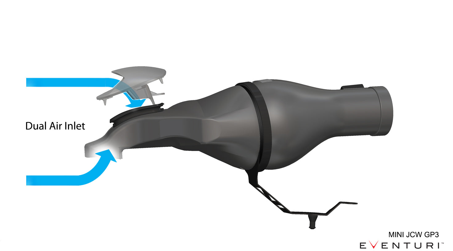
The OEM intake system draws in air from behind the front grill, above the radiator. The openings for the intake of ambient air are relatively small and therefore can lead to heat soak of the intake especially on a tuned Mini. The OEM bonnet scoop does not provide air directly to the intake and since the bonnet already has 2 cut-outs under the scoop, we decided to utilise this feature and redevelop the scoop. Our scoop is a direct replacement of the OEM part and clicks into place using the same fastening method. It features 2 inlet ramps which guide external air through the existing cut-outs on the bonnet and into the inlet duct (see below). As the car speeds up, more air is forced into the duct keeping inlet temperatures to a minimum and avoiding the heat soak issue. The scoop has a redesigned profile with a longer top surface to cover the openings which also provides a more aggressive look. Crafted from 100% prepreg carbon fibre, the scoop provides an incredible aesthetic to the vehicle. To further enhance the aesthetic feature - we used a V-shaped split weave with the carbon to give a symmetrical profile which works well as the scoop sits in the middle of the bonnet.
By making use of the existing openings in the bonnet - the ramps on the carbon scoop extend through and guide the airflow into the duct. Here is the underside of the bonnet with the scoop installed.
Inlet Duct
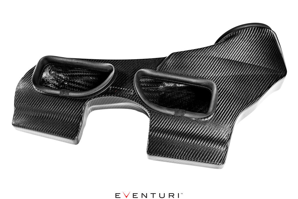
The OEM duct only draws air from behind the front grill and is very shallow over the slam panel. We have redesigned the duct to allow air in from the grill and also from the scoop. Furthermore, our duct has a much larger internal volume which allows the intake system to breath with less restriction. In order to protect against engine bay heat - the duct has a flexible rubber edging around the openings to the underside of the bonnet which seals to the bonnet once closed. It also has an expandable rubber edging around the opening to the filter housing which ensures a good seal to the filter as well as allowing movement with the engine.
Water Drainage
Since we have a direct airflow path to the filter, it is important that we also allow for water to be drained before reaching the filter. In order to protect against excess water ingress, we have designed several features into the intake components as follows.
- The top of the scoop covers the openings which stops rainfall entering the duct when the car is at a standstill.
- The scoop has 2 flow directing ramps which also act as a water barrier by forcing the water to fall down onto the base of the duct rather than moving straight to the filter area.
- The duct has 2 openings to allow water to drain out - above the radiator and also a drain hole before the filter housing connection.
- The face of the duct as it meets the filter housing has a wall on which the rubber edging is secured. This wall stops any build up of water from directly entering the filter and water is drained through the extra drain hole.


